Pusher Assembly :
The Pusher assembly is described in further detail with the aid of the diagram shown below:
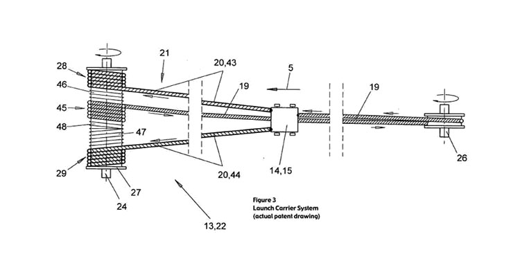
The Diagram shows the simple nature of the pusher assembly. Three cables (28, 45, and 29) are attached to the winding drum (24) and rest inside two sets of grooves (46, 48) . The two outer cables (28, 29) pull the pusher as the drum spins during the launch sequence, in turn propelling the train. The middle cable (45) is wound in an opposite direction, and rests in its own groove (48) which is also oriented in an opposite direction. The reason for this is because the middle cable must be drawn in while the motor is spinning in reverse after the launch has completed in order to reel in the pusher.
More of this project work will be uploaded soon. Please keep reading!
Note : This work was the final design project of the author and Matt Prussein, both who are currently senior Mechanical and Aerospace students at the University at Buffalo.

1 comment:
This design has been programmed by the professional and it has been perfectly design in my opinion. I am convinced to see this post because I have been looking for the one from a while.
Post a Comment