 Continued..
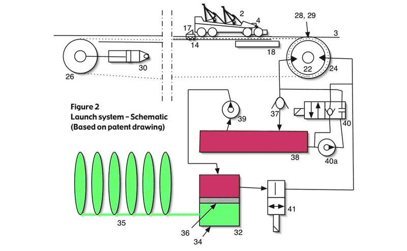
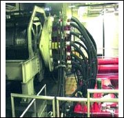
As previously mentioned, the launching system for the Top Thrill Dragster is based on hydraulics. The system is actually made up of two identical hydraulic systems. Each system iscomprised of 16 hydraulic motors, each fed by its own pump. The above schematic shows thebasic operation of the system by targeting a single motor and pump configuration. The picturebelow shows one of the actual systems connected to the drum. The other is located on the opposite side of the drum.
The key components are as follows:
14 - Pusher
22 - Reversible Hydraulic Motor
24 - Cable Winding Drum
32 - Cylinder
34 - Nitrogen filled chamber
35 - Collection of gas filled bottles
36 - Piston
38 - Fluid reservoir
39 - Electric Fluid pump
The rapid acceleration of the Top Thrill Dragster is achieved by storing large amounts of energy and quickly releasing it, much like slowly pressing down on a spring and letting go to release its potential energy. Energy in this system is stored by compressing nitrogen gas (34) in a cylinder (32). The electric fluid pump (39) supplies hydraulic fluid (oil) from a reservoir (38), to the top portion of the cylinder (32). The fluid being pumped into the cylinder (32) pushes down on the piston (36), forcing the nitrogen gas under the piston into a group of bottles already filled with compressed nitrogen (35). (The bottles in the diagram are not drawn in proportion to the cylinder, in actuality, the cylinder will be much larger in relation to the bottles.) Eventually all of the nitrogen from the cylinder makes its way into the bottles. It is now compressed to a much higher pressure, since the same nitrogen gas that filled both the cylinder and bottles is now confined to a much smaller volume in that of the bottles. At this point the system is charged and the rollercoaster is ready to be launched. The launch sequence is initiated when the valve (41) is quickly opened, rapidly releasing the highly compressed nitrogen gas causing a powerful flow of hydraulic fluid from the cylinder (32). It is here that the force is magnified, described in the above briefing, as the area of the fluid flow is greater than that of the nitrogen. The fluid travels via a hose through the right side of the hydraulic motor (22) and out the left, acting as a turbine to spin the cable winding drum (24) located under the track in front of the train. The spinning drum acts like a large fishing reel spinning at 500 rpm, pulling a series of launch cables (28, 29) attached to a "pusher" (14). The pusher is located directly behind the train and rides inside a slot located between the tracks. As it accelerates, it pushes the train (2) along the launch track.
After the launch is completed, the valve (41) closes, cutting off flow from the cylinder, and the other pump (40a) is switched to the position represented in the diagram. In this position, fluid is supplied to the left side of the hydraulic motor, thereby reversing the direction of the drum. This is necessary in order to bring the pusher (14) back to its original position for the next launch. The pusher assembly comes next.
To be contd...

No comments:
Post a Comment