Monday, October 16, 2006

What Muscles Are You Using to Pedal?


Source


I also read the book Biomechanics of Sport, by Christopher L. Vaughan and obtained the following neat little table on page 312. EMG analysis of muscles were done in 5 different cycling scenarios and the results show which muscles are used predominantly when.

*  *  *

Monday, October 9, 2006

Letchworth State Park Ride


Me and another friend, Larry Mordue (also a patrol officer for WNYMBA) drove up today to Letchworth State Park. It was a nice day off from school, sightseeing the sheer wonder of what many claim is the "Grand Canyon of the East". I rightly think that should be the case. We also did some road biking on the hills and had a chance to see the Annual Crafts Fair that usually runs in October. Plenty to see, and a great day out. Catch all the pictures we took today (some breathtaking) here. Thanks for reading!

Saturday, October 7, 2006

Top Thrill Dragster Redesign Concept - Part 6 (contd..)

These factors all have a hand in the way the human body will react to the force.But beyond all the research that the committee collected and analyzed to develop this standard, one of the most convincing pieces of evidence that roller coasters are safe is a study published in October 2002 in the Journal of Neurotrauma by University of Pennsylvania researchers Dr. Douglas H. Smith and Dr. David F. Meaney. The study attempts to produce “any sound evidence or analysis directly linking roller coasters with brain injury,” by using a mathematical model to determine the effects of three popular coasters in the U.S.—Rock ’n’ Roller Coaster at Disney MGM Studios in Florida; Speed, The Ride at the Nascar CafĂ© in Las Vegas and Face Off at King’s Island in Ohio. Smith and Meaney, a neuroscientist and a bioengineer, concluded that roller coasters do not cause brain injury.

On the ride into the future, roller coaster design will undoubtedly branch off into

unmarked territory, unforeseen by the designers and riders of today. But for now, launch

systems, namely hydraulic and pneumatic are the state of the art standard.

Top Thrill Dragster Redesign Concept - Part 6

VI.RESEARCH

Research today on roller coaster launch methods is primarily focused on improving the systems already in use. The two systems that show the most promise are hydraulic and pneumatic systems. This is apparent by the record boasting speeds and heights of hydraulic roller coasters, and the mind blowing acceleration achieved by pneumatic systems. A chart located at the end of this document shows the statistics on the tallest and fastest of each kind of roller coaster. The numbers show the superiority of these systems over the others, as well as traditional lift hill coasters, where gravity is the limiting factor for acceleration.

Research on Hydraulic systems is aimed at making them more reliable, trying to avoid the problems with faulty cables that have plagued the Top Thrill Dragster. Additionally increased speed and acceleration are being sought. Improvements in both performance and reliability have taken place, as proven by the success of the Kinga Ka.

Research on human reactions to these extreme rides has become an issue, since they are continually pushing the limits on what humans can endure. Politicians and critics alike have taken shots at the bodily harm that roller coasters using these new launch systems are capable of imposing on people.

It has long been known that speed is not the issue. It’s the change of direction that actually limits the body’s tolerance to force and causes stress to the cardiac system. According to Harold Hudson, chairman of the subtask group that developed new standards for measuring and limiting G force (ASTM F-24), a misunderstanding about the relationship between G force and speed was the major cause of the criticism from the media and various politicians. This onslaught suggested that rider injuries and even death were the direct result of the industry’s reckless need to produce higher and faster rides that bring people to the park.

One major aspect of G forces that’s often misunderstood is that G force is not just

one measurement. Acceleration in three axes is considered in design: vertical (up and

down), lateral (side to side), and fore and aft (ahead and behind). One has to be very

specific about what axis is talked about because requirements for lateral are very different

from vertical requirements for G forces. It’s important that one is focusing on the

magnitude of the G force and also duration as well as the onset—how quickly the G force

is applied to a human and how quickly it’s taken away.

Top Thrill Dragster Redesign Concept - Part 5 (Contd..)

In June 2005, the Dragster, in the midst of normal operation, stopped dead in its track at the very peak of ascent. It remained there for almost 20 minutes until maintenance could get to it via an elevator, needless to say that such a situation in its initial moments of taking place would have caused sufficient fear and anxiety for the passengers as well as their families and friends watching below. This problem could happen in the future, unless a contingency plan is developed instead of choosing to elevate a crew member up to 420 feet in the air to resolve the issue. We feel that :

The kinetic energy imparted could have an extra margin of safety just to ensure that it clears the top. Some kind of chain or pusher mechanism can be included in the track design for the peak portion of the ride which could kick in at times such as the one mentioned above.

Through proper communication with the public regarding comfort and ergonomic issues , and subsequent analysis and redesign, the ride can be greatly improved and people will be greatly satisfied with the thrill and the added comfort and safety.

Top Thrill Dragster Redesign Concept - Part 5

IV. REDESIGN

CABLES :


First and foremost, if the diameter of the cables was increased in size they would experience less stress since the tensile load would be distributed to a larger area. In order to apply this idea, a new drum would have to be used as well since the grooves cut into the drum are specific to the size of the cables. This could get costly and would have been easiest if incorporated into the original design where only the added cost of the thicker cable would be a factor.

Another way to make the cable more durable would be to use a different material. The material used for the cables is presently a form of steel, and may or may not have been changed since the original cable broke (refer to FAILURE). Using an alternate material could be done without having to replace other components, but once again the cost would increase. The cost to repeatedly replace failing cables coupled with the lost revenue from potential customers who wouldn't be too interested in hopping on a ride that is down with failures suggests that it may be cheaper in the long run to use a stronger and more expensive material.

LUBRICATION :

Frictional wear and tear could be reduced if some kind of lubricant were put in place. This would minimize contact forces among the cables and the drum, but might also present adverse effects. Corrosion from this lubricant could decrease the strength of the cables. Analysis of different kinds of lubrication would need to be performed to see if the reduction in friction would out-weigh the reduced strength of the cables. If so, this would be a relatively cheap and simple way to improve the life and reliability of the part.

Noise Reduction :

A potential problem in hydraulic systems is noise generation. Although they are quieter than pneumatic systems that have air compressors and air filtration units, hydraulic pumps can create noise through small variations in the fluid moving through the pump.

In a roller coaster such as the Dragster, where speeds can reach up to 120mph, any small effort made to improve comfort level will be greatly appreciated by the public, especially in the area of noise generation. Customers ride the Dragster simply for the fun and thrill and are largely unconcerned about the abstract mechanisms of the coaster. Any unwanted noise could potentially raise alarms among them (if not to say that it will bring about a nauseating factor), considering the fact that there have been malfunctions in the past with the system.

3 ways we feel this could be potentially achieved are by :

1. Researching and developing quieter piston systems for the cylinder.

2. Looking at new ways of mounting and housing the system.

3. Designing the hydraulic system to run at low motor speeds without compromise in overall performance of the coaster.


Top Thrill Dragster Redesign Concept - Part 4

III. FAILURE

Since there are more interacting parts utilized with a hydraulic launch system as opposed to a magnetic one, parts are more likely to fail.

The part that seems like it would be the most likely to fail are the cables (28, 29) that pull the pusher, shown above. These cables are responsible for transferring all of the energy produced by the 32 hydraulic motors to the train. A great deal of tension is placed on these cables as it accelerates the coaster weighing, 15,000 lbs with passengers, from zero to 120 mph in 4 seconds. The stresses on these cables will fluctuate from minimum value, while the ride is idle, to some maximum value as they pull the pusher. Hence, fatigue will eventually occur.

This has in fact been the case several times during the early operating life of the ride. The expected life of this part is unknown but it seems reasonable that the designers only planned to replace the cable once or twice a season, in order to prevent failure.

So far the cables have not been lasting that long, the first one breaking after just 22 days of operation. Because of the relatively cheap cost of the cable, as well as the strength requirements, repair of the cable is not practical, in the event of failure the part is replaced. During this first failure, the part was replaced that day and operation resumed the next day. Repair would not have been much quicker if quicker at all, and would almost certainly leave the part weaker than before it had broken anyway.

The drum (24) is a shaft supported on two ends with bearings. And is subjected to fluctuating loadings due to the tension in the ropes. Hence, it can be considered as subjected to a distributed load of different magnitude in different parts of the shaft.

The free body diagram of the drum(24) can be approximated as shown below ( ignoring the angles of the cables). A torque not shown would also be acting on the drum shaft in either direction depending on if it is launching the coaster or retrieving the pusher.

The direction of the wind for cable (45) is reversed from the wind of cables (28) and (29). This means as the tension of cables 28 and 29 is maximum the tension of cable 45 is zero. The direction of rotation of the drum also reverses, This means the drum is subjected to a fatigue load. The torque also reverses direction and fluctuates from zero to maximum likewise.

Going back to the launch cables, it is pretty obvious from their function that the main force acting on them will be tensile. The loads that they will carry will be large in order to achieve such high accelerations on such a massive object (the 15,000 lb train).

In addition to tensile forces, there are undoubtedly frictional forces. The cables that are wound around the drum experience friction with both the drum and themselves. This friction can become significant as the cables are wound tightly and move rapidly as the drum spins, possibly contributing to the repeated failure of the cables.

Two of the launch cables act while launching, while the other one acts to pull back the pusher. Since each set of cables serves only one function, and acceleration during both of these operations is uniform, there is a minimal range of loads.

The environment most certainly plays a role in the fatigue failure process. The cables that pull the pusher are located directly under the track and are exposed to the environment. Because the ride is located in Sandusky, Ohio, and operates from spring to fall, it experiences a wide range of weather conditions. Rain, humidity, and changes in temperature all add together to shorten the ideally expected life of the part. The extent to these affects, as well as the aforementioned frictional affects may have been underestimated by the designers, causing for the many unexpected failures.

Top Thrill Dragster Redesign Concept -Part 3 (Contd..)

Contd...

Pusher Assembly :

The Pusher assembly is described in further detail with the aid of the diagram shown below:

The Diagram shows the simple nature of the pusher assembly. Three cables (28, 45, and 29) are attached to the winding drum (24) and rest inside two sets of grooves (46, 48) . The two outer cables (28, 29) pull the pusher as the drum spins during the launch sequence, in turn propelling the train. The middle cable (45) is wound in an opposite direction, and rests in its own groove (48) which is also oriented in an opposite direction. The reason for this is because the middle cable must be drawn in while the motor is spinning in reverse after the launch has completed in order to reel in the pusher.

More of this project work will be uploaded soon. Please keep reading!

Note : This work was the final design project of the author and Matt Prussein, both who are currently senior Mechanical and Aerospace students at the University at Buffalo.

Top Thrill Dragster Redesign Concept -Part 3 (Contd..)

Continued..

As previously mentioned, the launching system for the Top Thrill Dragster is based on hydraulics. The system is actually made up of two identical hydraulic systems. Each system iscomprised of 16 hydraulic motors, each fed by its own pump. The above schematic shows thebasic operation of the system by targeting a single motor and pump configuration. The picturebelow shows one of the actual systems connected to the drum. The other is located on the
opposite side of the drum.

The key components are as follows:

14 - Pusher
22 - Reversible Hydraulic Motor
24 - Cable Winding Drum
32 - Cylinder
34 - Nitrogen filled chamber
35 - Collection of gas filled bottles
36 - Piston
38 - Fluid reservoir
39 - Electric Fluid pump


The rapid acceleration of the Top Thrill Dragster is achieved by storing large amounts of energy and quickly releasing it, much like slowly pressing down on a spring and letting go to release its potential energy. Energy in this system is stored by compressing nitrogen gas (34) in a cylinder (32). The electric fluid pump (39) supplies hydraulic fluid (oil) from a reservoir (38), to the top portion of the cylinder (32). The fluid being pumped into the cylinder (32) pushes down on the piston (36), forcing the nitrogen gas under the piston into a group of bottles already filled with compressed nitrogen (35). (The bottles in the diagram are not drawn in proportion to the cylinder, in actuality, the cylinder will be much larger in relation to the bottles.) Eventually all of the nitrogen from the cylinder makes its way into the bottles. It is now compressed to a much higher pressure, since the same nitrogen gas that filled both the cylinder and bottles is now confined to a much smaller volume in that of the bottles. At this point the system is charged and the rollercoaster is ready to be launched. The launch sequence is initiated when the valve (41) is quickly opened, rapidly releasing the highly compressed nitrogen gas causing a powerful flow of hydraulic fluid from the cylinder (32). It is here that the force is magnified, described in the above briefing, as the area of the fluid flow is greater than that of the nitrogen. The fluid travels via a hose through the right side of the hydraulic motor (22) and out the left, acting as a turbine to spin the cable winding drum (24) located under the track in front of the train. The spinning drum acts like a large fishing reel spinning at 500 rpm, pulling a series of launch cables (28, 29) attached to a "pusher" (14). The pusher is located directly behind the train and rides inside a slot located between the tracks. As it accelerates, it pushes the train (2) along the launch track.

After the launch is completed, the valve (41) closes, cutting off flow from the cylinder, and the other pump (40a) is switched to the position represented in the diagram. In this position, fluid is supplied to the left side of the hydraulic motor, thereby reversing the direction of the drum. This is necessary in order to bring the pusher (14) back to its original position for the next launch. The pusher assembly comes next.

To be contd...


Top Thrill Dragster Redesign Concept -Part 3

II. SYSTEM DESCRIPTION


Hydraulic machines work on the basis of the following principles :

1. Liquids are incompressible.

2. Pascal's Law : "A change in applied pressure on a fluid is transmitted undiminished to every

point of the fluid and the walls of the container."

3. Pascal's Law implies 'Force Multiplication Capability."

If one has two cylinders connected together, a small one and a large one, and apply a small Force to the small cylinder, this would result in a given pressure. By Pascal's Principle, this pressure would be the same in the larger cylinder, but since the larger cylinder has more area, the force emitted by the second cylinder would be greater. This is represented by rearranging the pressure formula P = F/A, to F = PA. The pressure stayed the same in the second cylinder, but Area was increased, resulting in a larger Force. The greater the differences in the areas of the cylinders, the greater the potential force output of the big cylinder.

This is mainly how a hydraulic system, such as a vehicle lifting mechanism, works.

Tp be continued in part 4..


Top Thrill Dragster Redesign Concept -Part 2


It was these LIM and LSM launched coasters that marked the beginning of the evolution of launch systems from space saving looping coasters to extreme thrill rides that aim for high speeds, acceleration, and heights in simple designs that usually consist of nothing more than one large hill. Superman the Escape, at Six Flags Magic Mountain embraced this concept in 1997, reaching a maximum speed of 100 miles per hour in just 6 seconds, and climbing to a height of over 400 feet, making it the tallest and fastest roller coaster of its day, the next tallest being the Desperado at the Buffalo Bill Casino in Nevada, at a mere 225 feet. The ride was magnetically launched, and consisted of one hill in which the riders would ride to the top and then ride down backwards after climaxing.

Launch systems currently lead the way in the fierce competition for the most extreme roller coasters. The current tallest roller coasters in the world use launch systems and are about 100 feet taller and 30 miles per hour faster than the tallest traditional lift hill coasters. As a result, new launch systems are being explored in order to output the greatest speeds and accelerations, to deliver the maximum thrill that coaster enthusiasts demand.

In 2002, the first hydraulic launch system was developed by Intamin AG, and was used on Knott’s Berry Farm’s Xcelerator. A year later, the world was introduced to the Top Thrill Dragster at Cedar Point in Ohio. Its hydraulic launch system launched it past Superman the Escape as the tallest, and fastest roller coaster at the time. It reached a speed of 120 miles per hour in 4.2 seconds, climbing to a height of 420 feet. It has only been surpassed by the Kinga Ka, of Six Flags Great Adventure in Jackson, New Jersey, which features a nearly identical hydraulic launch system also designed by Intamin AG. The Kinga Ka hits 128mph - considerably faster than the 50mph that was around only 25 years ago!

It seems for now, that hydraulic launch systems are the way to go.

Top Thrill Dragster Redesign Concept -Part 1

The history of modern roller coasters can be traced back to 15th century Russia. Russia has always suffered extremely cold winters due to its northern latitude. At some point during the 15th century, people had the idea that they could use the copious amounts of ice and snow as a form of amusement. They built sleds and used an iced-up wooden slope to serve as the track. This was the first major step in ride development; the deliberate construction of a slope for the specific purpose of carrying passengers for pleasure. They were eventually known as the Russian Mountains.

From sleds and ice roller coasters began to take shape when mine carts were used to provide amusement. These “rides’ popped up on hills after old railway tracks were no longer in use. They were essentially run away mine carts with no mechanical components and few safety considerations.

It wasn’t until 1826 in France, that mechanical components were incorporated into “roller coasters”. The cars on these rides were anchored to the track by an extension of the wheel axles projecting into grooves in the sides of the track, later, cables would be added. These new features allowed for speeds of about 30 miles per hour. Just like the Russian Mountains, these carts were powered by gravity, and in order for the ride to begin, the carts had to manually be pushed to the top of a hill.

The first modern roller coaster is considered to be the Switchback Railway, built by La Marcus Adna Thompson, in 1884, operating in Coney Island, New York. This ride was much like a Russian Mountain with mine carts in place of sleds, and a track in place of ice. A year later the first closed circuit coaster was implemented, and shortly after a lift hill was introduced to take over the chore of lifting the cart to the top of the hill.

The 20th century saw the large scale development of the modern day roller coaster. Initially, these attractions were made of wood, closed circuited, and all possessed the same basic features. Just like their predecessors, these roller coasters were all powered by the potential energy that they acquired at the beginning of the ride. This energy was now obtained by mechanically pulling the train up a lift hill, as opposed to being manually pushed.

For years to come advances in technology would change many of the major features of roller coasters. Steel tubular tracks were introduced in 1959, allowing for new design features. These included suspended, stand up, and looping roller coasters, developed during the 70’s and 80’s. It was around this time that launching systems were also conceived.

Launching systems were first developed so that looping roller coasters could be built in parks that didn’t have enough room for traditional closed circuit tracks. These rides would launch, go though a series of twists, turns and loops, and make their way up a ramp until they briefly came to rest . They would then make their way down this ramp backwards and run the course in reverse.

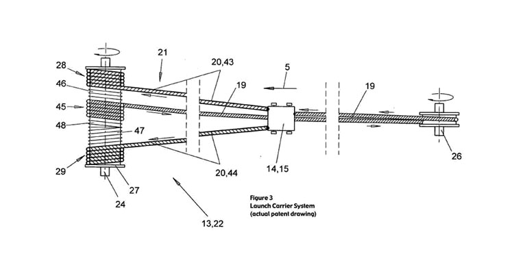
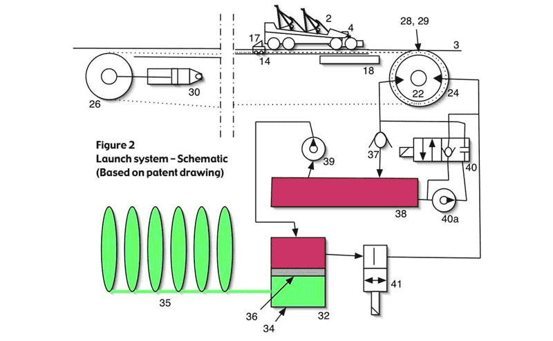
The first of these was built in 1977 and was dubbed the Schwarkzkopf Shuttle Loop. It was propelled by dropping a 40 ton weight from a nearby tower. The weight was connected to a pusher, by a clutch and cables. As the weight fell the cables would pull the pusher, which rode in a slot in between the track’s rails. The pusher, located behind the train, would then push the train down the track.

At about the same time flywheel systems and electric motors were aslo designed. A motor, would spin a flywheel to high speeds and when ready to launch it would grab a cable and accelerated the train using a similar pusher system. Although they could achieve sufficient amounts of power, they were plagued by mechanical problems.

In order to overcome these problems, magnetic launch systems were devised in the mid 1990’s dubbed LSM (Linear Synchronous Motor) and LIM (Linear Induction Motor). The principle behind these systems was to use electrically charged magnets to propel a train down a track. Physical contact was not needed between parts, and the system as a whole was much more reliable and low maintenance. This system was first used on the Outer Limits Flight of Fear, located in Paramount’s Kings Dominion in Virginia, in 1996. Although this ride was a traditional closed circuit coaster, the majority of launched coasters are not.

Sunday, October 1, 2006

How Will a Mechanical Engineer Write a Love Letter?

I got this in a forwarded mail. Its pretty hilarious.

How will a Mechanical Engg write a love letter?

My Dear Love

From the day you entered in the control volume of my mind my heart has become a closed system and its entropy is increasing according to the 3rd
law of loveodynamics.......

The events and activities are so complex that i cannot find the optimum path after n number of iterations......

My heart is unable to sustain the cyclic load of your frequent smiles and is near to endurance limit failure.....

I am quenched in your thoughts and no heat treatment can save my heart from decrystalisation now........

Please do not test the bearing capacity of my heart valves and lower your yield strength.........

Please do not increase the compression ratio of my heart so much because it is not designed to bear so much thermal stress.....

Please lower the octane number of your temper as my little heart is not accustomed to so much undesired Knocking.......

I'm sure that you would also be experiencing some residual stress, and will someday show a proportionate straining of your heart according to hooks law..........


..........and as a Mechi I firmly belive in this theory.....so i will
wait

........ till my little heart crosess its ultimate tensile stress and
fractures.


Your Hardened lover,


Mechanical Engineer...